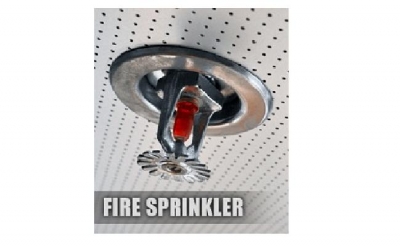
Sprinkler Systems:
A fire sprinkler system is an active fire protection measure, consisting of a water supply system, providing adequate pressure and flow rate to a water distribution piping system, onto which fire sprinklers are connected. Although historically only used in factories and large commercial buildings, systems for home and small building are now available at a cost-effective price. Fire sprinkler systems are extensively used worldwide, with over 40 million sprinkler heads fitted each year. In buildings completely protected by fire sprinkler systems, over 99% of fires were controlled by fire sprinklers alone.
Sprinkler activation will do less damage than a fire department hose stream, which provides approximately 900 liters/min (250 US gallons/min). A typical sprinkler used for industrial manufacturing occupancies discharge about 75-150 liters/min (20-40 US gallons/min). However, a typical Early Suppression Fast Response (ESFR) sprinkler at a pressure of 50 psi (3.40 Bar) will discharge approximately 378 liters/min (100 US gallons/ minute).
In addition, a sprinkler will usually activate between one to four minutes, whereas the fire department typically takes at least five minutes to arrive at the fire site after receiving an alarm, and an additional ten minutes to set up equipment and apply hose streams to the fire. This additional time can result in a much larger fire, requiring much more water to extinguish.
{tab=Sprinkler Head}
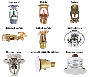 Fire sprinklers can be automatic or open orifice. Automatic fire sprinklers operate at a predetermined temperature, utilizing a frangible glass bulb containing liquid which breaks, allowing the plug in the orifice to be pushed out of the orifice by the water pressure in the fire sprinkler piping, resulting in water flow from the orifice. The water stream impacts a deflector, which produces a specific spray pattern designed in support of the goals of the sprinkler type. The majority of automatic fire sprinklers operate individually in a fire.
Open orifice sprinklers are only used in water spray systems or deluge sprinklers systems. They are ide
ntical to the automatic sprinkler on which they are based, with the heat sensitive operating element removed.
Automatic fire sprinklers utilizing frangible bulbs follow a standardized color-coding convention indicating their operating temperature. Activation temperatures correspond to the type of hazard against which the sprinkler system protects.
Pattern type:
- Pendent
- Concealed Pendent
- Upright
- Sidewall
- ESFR (Early Suppression Fast Response)
{tab=Wet Alarm Valve}
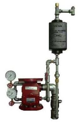
The valve is designed to initiate an alarm during a sustained flow of water (such as the flow required by an open sprinkler) by operating an water motor alarm and/or alarm pressure switch.
The valve is made suitable for use on variable pressure water supplies by adding the retard chamber to the standard trim.
{tab=Valve}
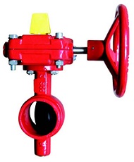 - Butterfly valve with Tamper switch :
Each zone in sprinkler system shall be separated with a listed butterfly valve equipped with tamper switch to
supervise open/ close condition of valve.
Max. Working pressure up to 300 Psi (20.7 Bar)
Size: 1” thru 12”
Connections:
- Wafer Type to match between two Flanges (DIN or ANSI)
- Grooved Type
- OS&Y Gate Valve with supervisory Switch :
Acc. To NFPA 13, Valves on connections to water supplies, sectional control and isolation valves, and other valves in supply pipes to sprinklers and other fixed water based fire suppression systems shall be supervised by Central station, proprietary, or remote station signaling service.
The Switch is used to monitor the open position of an OS&Y (outside screw and yoke) type gate valve. These switches mount conveniently to most OS&Y valves ranging in size from 2" to 12".
- Test & Drain Valve :
Acc. To NFPA13, Provisions shall be made to properly drain all parts of the system.
(Wet Pipe System) test connection is permitted to terminate into a drain capable of accepting full
flow using an approved sight test connection containing a smooth bore corrosion-resistant orifice
giving a flow equivalent to one sprinkler
To comply NFPA Code it shall be permitted to be installed in any location downstream of the water
flow alarm (Flow Switch).
Available sizes are ¾” thru 2” UL Listed/ FM Approved.
{tab=Switches}
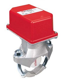 - Flow Switch :
Acc. To NFPA 13, Water flow alarm devices shall be installed that any flow of water from a sprinkler system
equal to or greater than that from a single automatic sprinkler of the smallest orifice size installed on the
system will result in an audible alarm on the premises within 5 minutes after such flow begins and until such
flow stops.
It is available for installation on steel pipes size 1” thru 8”.
- Pressure Switch :
The Water Pressure Actuated Switches are designed for the detection of a water flow condition in automatic
fire sprinkler systems of particular designs such as wet pipe systems with alarm check valves, dry pipe,
pre-action, or deluge valves. It’s adjustable between 4 and 15 psi (0.27 and 1.03 BAR).
Air supervisory pressure switches also used in dry pipe system to detect pressure loss in air supply it is
factory set for 40 PSI (2,8 BAR) normal system pressure and set to operate at a pressure decrease of 10 PSI
(0.7 BAR) at 30 PSI (2.1 BAR). It is possible to change set points other than factory set point if required.
- Valve Position Supervisory Switch :
The OSYSU is used to monitor the open position of an OS&Y (outside screw and yoke) type gate valve.
This device is available in two models; the OSYSU-1, containing one set of SPDT (Form C) contacts
and the OSYSU-2, containing two sets of SPDT (Form C) contacts.
These switches mount conveniently to most OS&Y valves ranging in size from 2" to 12" (50mm to 300mm).
They will mount on some valves as small as ½" (12,5mm).
{tab=Pressure Control}
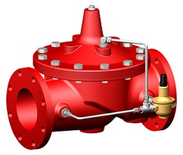 - Pressure Reducing Valve :
Acc. To NFPA 13, In portions of systems where all components are listed for pressure of 175 psi (12.1 bar)
and the potential exists for normal (non-fire condition) water pressure in excess of 175 psi (12.1 bar),
a listed pressure reducing valve shall be installed and set for an outlet pressure not exceeding 165 psi (2.4 bar)
at the maximum inlet pressure.
Pressure Reducing Valves automatically reduce a higher inlet pressure to a steady lower outlet pressure regardless
of changing flow rate and/or varying inlet pressure. The valves pilot control system is very sensitive to slight
downstream pressure fluctuations, and will automatically open or close to maintain the desired pressure setting.
- Pressure Relief Valve :
Acc. To NFPA 13, A relief valve of not less than ½ in. (13 mm) in size shall be provided on the discharge side
of the pressure reducing valve set to operate at a pressure not exceeding 175 psi (12.1 bar).
Fire Protection System Service Using the pressure relief valve in a fire protection system or
other closed type system, prevents pressure build-up whenever line pressure exceeds the setting of the spring.
The valve will relieve excess pressure to atmosphere preventing damage to the distribution network.
{tab=Dry Pipe System}
- Dry Pipe Valve :
Dry Pipe Valve makes possible the installation of automatic sprinkler systems in buildings in which
freezing temperatures prevail. This type of system, called a Dry Pipe System, has air under pressure
instead of water in the piping above the dry pipe valve. When one or more automatic sprinklers operate
due to fire, the air pressure in the system is reduced the dry pipe valve opens and water under pressure flows
in the activated sprinkler(s) and is then distributed on the fire.
When an automatic sprinkler operates, the resulting air pressure decay is inversely proportional to the size
of the dry system – the larger the system, the slower the air pressure decays which slows the operation
of the Dry Pipe Valve. NFPA 13, Installation of Sprinkler Systems, specifies that quick opening devices
may be required in dry systems having capacities of more than 500 gallons.
- Air compressor :
Dry and Pre-action Systems require a dependable source of clean dry air under the proper pressure.
The air supply must be adequate to restore normal air pressure within a time specified by the
authority having jurisdiction. NFPA Requirements is 30 minutes for dry pipe systems.
Proper air regulation should be provided for all dry systems and is extremely important.
If pressure is too low, the dry valve may accidentally trip when subjected to surges in water supply pressure.
If pressure is too high, the time between the opening of a sprinkler and the flow of the water from
the sprinkler may be unacceptably long. Very high pressure also can damage the dry valve.
Design air pressure is specified by the dry valve manufacturer.
The dry system is filled from a constant source of air such as an automatic air compressor.
- Air Maintenance Device (AMD) :
The air pressure in the system is maintained by the air pressure maintenance device which is set at design pressure.
The air maintenance device contains a 1/16 inch (1.6 mm) orifice which restricts the flow of air into the system
so that when a sprinkler opens, air pressure will not build up faster than it will discharge through a sprinkler.
The bypass valve is kept closed and opened only to speed up the filling of the system piping to the required pressure
in the required time.
{tab=Pipe}
NARFOAMKAR is able to procure Pipes for sprinkler system considering all aspects of NFPA-13 Standard which is
qualified and listed by Underwriter laboratories (UL).
Specifications:
Pipe Type: Electrical resistant welded (ERW)
Reference Standard: ASTM A53
Finishing: Galvanized
UL Listed Pipe Sizes:
- 1/2, 3/4, 1, 1-1/4, 1-1/2, 2, 2-1/2, 3, 4, 5, 6, 8, 10, and 12 in. (Sch.40)
- 10 and 12 in (Sch.20)
- 14 and 16 in (Sch. 10 & 30)
{tab=Fitting}
- Grooved Fittings:
The grooved piping system has been around for over 80 years, providing fast, easy and reliable piping assemble.
When the grooved components are connected by the shouldered gasket couplings, the result is a pressure tight
pipe system.
Grooved Fittings are UL Listed / FM Approved for size above 2 ½” up to 16” and for up to 300 Psi working
pressure.
Benefit of using Grooved systems using welded fittings:
- Threaded Fittings:
- Ability to use Galvanized pipe for longer system life
- Simple to do system, Less installation time and manpower required result in faster project progress
- Ease of access to pipe for modification or rotation
- Minimize noise and vibration
- Stress-free System
- Accommodates Misalignment and Joint Deflection
- No smoke or fire in work area
For pipe line 2” and smaller, threaded fittings are the best choice. They are UL Listed/ FM Approved for
a system with up to 300 Psi working pressure which satisfy most of sprinkler installations.
{tab=Hanger}
NARFOAMKAR Manufactures Sprinkler Pipe hangers and Rod Bolt to offer a complete sprinkler system to valuable
customers. Hangers are available from ½” Pipe size thru 8” fully
in compliance with ANSI/UL 203, “Pipe Hanger Equipment for Fire Protection Service”
They made by Cold rolled Galvanized steel sheet with appropriate Galvanized rod bolt to support sprinkler
pipe lines securely to building structure elements.
{tab=Fire Pump}
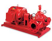
UL Listed/ FM Approved pump sets have different criteria than other regular pumps using in HVAC and plumbing systems. E.g. Pumps shall furnish not less than 150 percent of rated capacity at not less than 65% of total rated head.
NARFOAMKAR offers wide range of UL Listed/ FM Approved Fire Pump set skids preassembled with Driver (Electric or Diesel).
Jockey pump or pressure makeup pump also available to compensate normal leakage of system and maintain system pressure at non fire situation.
{/tabs}

